Configuring an analysis tool template |
|
|
To create or edit an analysis tool template, first access the PB019 (Configuration ▪To create a new template, click on the arrow next to the ▪To edit an existing template, locate and select the desired record and click on the
1 / 2
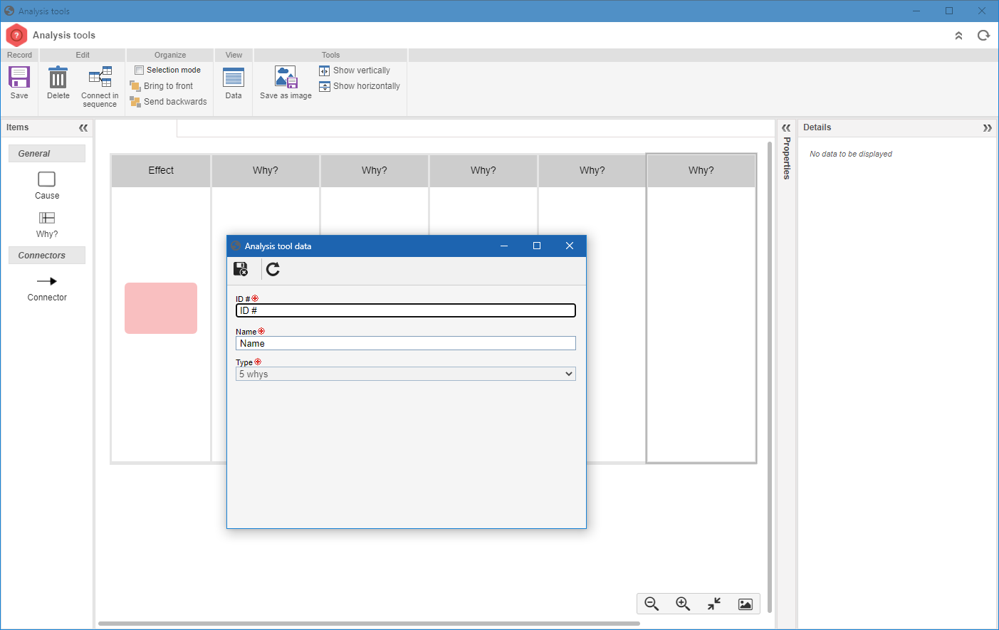
Analysis tool template data 2 / 2
5 Whys 2 / 2
Fault Tree Analysis - FTA 2 / 2
Ishikawa (6M)
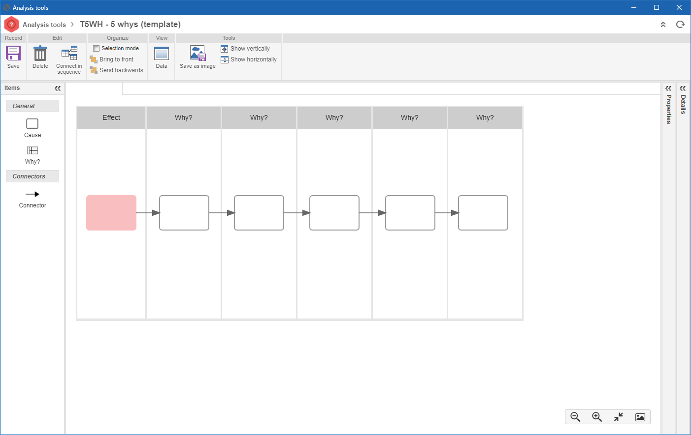
5 WhysDefine how many questions the template will have and how many causes each question will have. The "Effect" lane will display the problem to be analyzed. ▪Add question: To add a new question lane, drag the "Why?" element to the modeling area. The new questions will be added at the end of the list. ▪Delete question: To delete a question lane, simply select it in the modeling area and click on the "Delete" button. When deleting a question, if there are cause elements within the lane, they will also be deleted along with the question. If there are causes connected in a sequence, the cause connectors within the deleted lane will also be deleted along with the cause; in this case, it will be necessary to reconnect the remaining causes. ▪Add cause: To add a new cause, drag the "Cause" element to the modeling area, within the lane of a question. It is possible to associate one or more causes with the same question. ▪Delete cause: To delete a cause, select the desired cause and click on the "Delete" button. If there are causes connected in a sequence, the connectors of the deleted cause will also be deleted along with the cause; in this case, it will be necessary to reconnect the remaining causes. ▪Connector: This element allows connecting two causes in a sequence. To do that, click on the "Connector" element, then click on the first cause and on the second cause. At this point, both causes will be connected. ▪Connect in sequence: This feature allows connecting several causes in a sequence. To use it, select the causes in the same order in which the connectors will be applied and click on the "Connect in sequence" button.
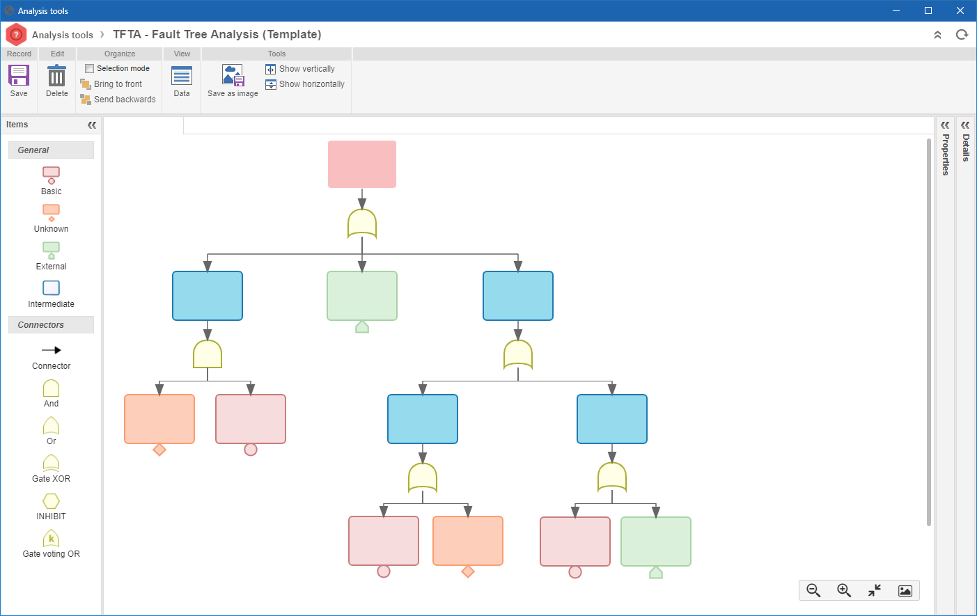
FTA (Fault tree analysis)The FTA (Fault Tree Analysis) diagram is used to identify the causes of problems through a logical relationship between primary (basic), external, intermediate, or unknown faults. The top of the structure displays the problem to be analyzed. Define the cause structure that the template will have. ▪Add elements (causes and logical connectors): Drag the cause elements (or failure type) according to their type: Basic, Unknown, External, or Intermediate. Drag the AND, OR, GATE XOR, INHIBIT, or GATE VOTING OR to define the logical relationship between the causes. ▪Delete elements (causes and logical connectors): To delete an element, select it and click on the "Delete" button. If the element is a cause, the logical connector that is connected to the sequence will also be deleted. If the element is a logical connector, only the connectors (arrows) that connect the logical connectors to the causes will be deleted. ▪Connector: This element allows connecting two elements in a sequence. To do that, click on the "Connector" element, then click on the first element and on the second element. At this point, both elements will be connected. ▪Connect in sequence: This feature allows connecting several structure elements in a sequence. To use it, select the elements in the same order in which the connectors will be applied and click on the "Connect in sequence" button.
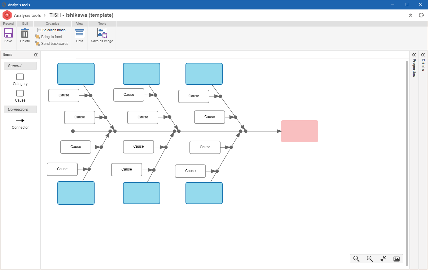
IshikawaThe Ishikawa diagram, also known as Cause and effect diagram or Fishbone diagram, is a chart that aims to organize the causes of a problem in several categories. In the 6M standard, the cause categories are: Method, Machine, Measurement, Environment, Material and Manpower. The modeling of the template starts with a horizontal arrow that points to a square (on the right) that contains the problem to be analyzed. Define the categories and causes that the template will have. ▪Add categories: Drag the categories of the possible problem causes. Use the "Details" panel to enter the name of each category. ▪Add causes: To add a new cause, drag the "Cause" element to the modeling area, next to a category. It is possible to associate one or more causes with the same category. ▪Connect category to the Ishikawa diagram: To perform this connection, click on the "Connector" element, then click on the category and on the problem. The connection arrow will be applied to the center of the diagram. Drag the tip of the arrow to the desired location. ▪Connect category to the category: To perform this connection, click on the "Connector" element, then click on the category and on the category. The connection arrow will be applied to the center of the arrow connected to the diagram. Drag the tip of the arrow to the desired location. ▪Delete causes: To delete a cause, select the desired cause and click on the "Delete" button. The causes connected to the deleted cause will also be deleted. ▪Delete categories: To delete a category, select the desired category and click on the "Delete" button. The causes connected to the deleted category will not be deleted.
|